Bridge Plugs & Cement Retainers

Bridge Plugs & Cement Retainers

Products

Kappa Bridge Plug

GO BACK
Blog Post
  • 100% CANADIAN MANUFACTURED
  • WIRELINE, HYDRAULIC , HYDRAULIC MECHANICAL (HM), HMII
  • 360 RETAINING RINGS TO ASSIST IN PREVENTING ELEMENT EXTRUSION
  • STANDARD VERSIONS UP TO 8 5/8 RATED UP TO 70 MPa (10,000 PSI) AT 150 C (300 F)
  • COMPATIBLE TO BOLT & ALPHA SETTING TOOLS AND ADAPTER KITS
  • AVAILBLE IN MID RANGE HIGH TEMPERATURE AT 200 C (400 F) AND THERMAL APPLICATION 425 C (800 F)

4-1/2" Through 20"

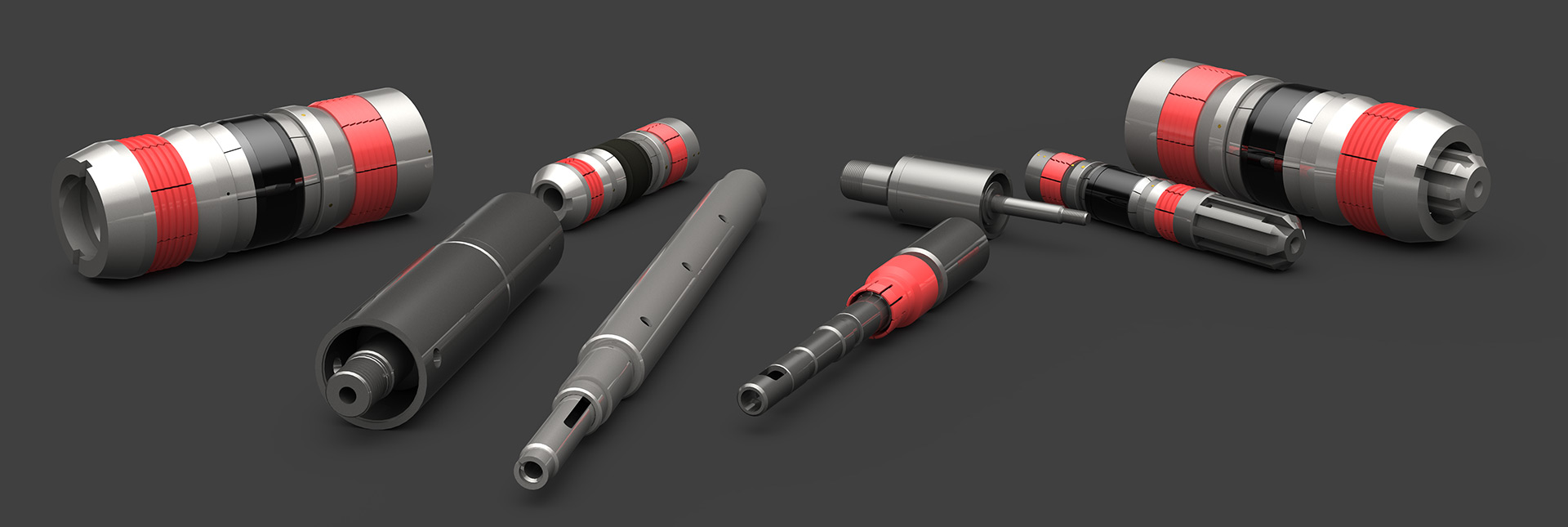
Canadian Downhole Inc.premium cast iron bridge plugs are designed to run on electric line(e-line).The Kappa bridge plug rated 2,000-psi to 10,000-psi differential (see specification guide) and 300°F,from above and below.

features

  • Field-proven design
  • Constructed of drillable materials
  • Standard packing element rated at 300°F
  • One-piece slips
  • Top set with shear stud

benefits

  • Rated to 2,000-psi to 10.000-psi differential, from above and below at 300°F. See Specification guide.
  • Runs on existing e-line setting tools
  • Sets in P-110 casing
  • Higher temperature packing elements available upon request
  • No tension mandrel required
  • Retaining ringsto assist in preventing element extrusion

applications

  • Well abandonment
  • Temporary and permanent zonal isolation
  • Squeeze cementing
  • Fracturing
  1. Install setting sleeve (1) on pressure setting tool.
  2. Install shear stud in (3) bridge plug.
  3. Install lock spring (2) on upper thread of shear stud (3). The lock spring (2) must be used to prevent the bridge plug from backing off of pressure setting assembly during run-in.
  4. Install bridge plugon pressure setting tool at shear stud (3). Thread the Bridge Plug to close gap between cap and setting sleeve. Ensure that there is a 1/8” -3/8” of clearance between setting sleeve (1) and cap.(CAUTION: DO NOT WRENCH. THIS OPERATION SHOULD BE DONE BY HAND.)
  5. Proceed by running to setting depth and setting as per wire line operating procedures.
  6. When pressure setting tool is removed from the well.remove setting sleeve for reuse.
bridge-plug-assembly-4.0-5.0-4-13
  1. Install adjuster sub (3) on pressure setting tool. Install set screw (2) In adjuster sub.
  2. Install setting sleeve (1) on pressure setting tool.
  3. Install lock spring (5) on upper thread of shear stud (4). The lock spring (5)must be used to prevent the bridge plug from backing off of pressure setting assembly during run-in.
  4. Install shear stud (4) in bridge plug.
  5. Install bridge plug on pressure setting tool at shear stud (4). Thread the Bridge Plug to close gap between cap and setting sleeve (1). Ensure that there is a 1/8” -3/8” of clearance between setting sleeve (1) and cap. (CAUTION: DO NOT WRENCH.THIS OPERATION SHOULD BE DONE BY HAND.)
  6. Proceed by running to setting depth and setting as per wire line operating procedures.
  7. When pressure setting tool is removed from the well.remove setting sleeve (1) and adjuster sub (3) for reuse.
bridge-plug-assembly-5_8-4-13
  1. Install adjuster sub (3) on pressure setting tool
  2. .Install set screw (2) in adjuster sub (3).
  3. Install setting sleeve (1) on pressure setting tool
  4. .Install lock spring (4) on upper thread of shear stud (5). The lock spring (4) must be used to prevent the bridge plug from backing off of the pressure setting assembly during run-in.
  5. Install shear stud (5) in the Bridge Plug.
  6. Install bridge plug on pressure setting tool at shear stud (5). Thread theBridge Plug to close the gap between the cap and setting sleeve (1). Ensure that there is a 1/8” -3/8” of clearance between the setting sleeve(1) andthe cap. (CAUTION: DO NOT WRENCH. THIS OPERATION SHOULD BE DONE BY HAND.)
  7. Proceed by running to setting depth and setting as per wire line operating procedures.
  8. When pressure setting tool is removed from the well, remove setting sleeve (1) and adjuster sub (3) for reuse.
bridge-plug-assembly-9_13-4-13

Kappa Cement Retainers

GO BACK
Blog Post
  • 100% CANADIAN MANUFACTURED
  • WIRELINE, HYDRAULIC OR MECHANICAL SETTING TOOL
  • 360 RETAINING RINGS TO ASSIST IN PREVENTING ELEMENT EXTRUSION
  • STANDARD VERSIONS RATED UP TO 70 MPa (10,000 PSI) AT 150C (300F)
  • COMPATIBLE TO BOLT & ALPHA SETTING TOOLS AND ADAPTER KITS
  • AVAILBLE IN MID RANGE HIGH TEMPERATURE AT 200 C (400 F) AND THERMAL APPLICATION 425 C (800 F)

4-1/2" Through 13-3/8"

The Kappa WHMcast iron drillable cement retainer's modular, field proven design makes it a versatile tool in a variety of applications. The Kappa may be set mechanically or on a wireline setting tool by changing the top slips. The Kappa also converts to a Kappabridge plug.

FEATURES

• Cast iron drillable design

• Simple, surface-controlled valve automatically closes when the stinger is removed

• Converts between mechanical or wireline set by changing top slips

• Components rotationally locked for easy drill out

• Temperature rating to 440°Fahrenheit

• Differential pressure rating to 10,000 psi thru 8-5/8”

BENEFITS

• Allows pressure-testing before squeeze

• Engineered Valve design protects sensitive zones in low-fluid wells

• Convertibility reduces inventory requirements

• Fast drill out saves rig time

APPLICATIONS

• Cementing

• Stimulation

• Well abandonment

• Temporary or permanent zone isolation

related products

• Stinger Seal Assembly

• MST Mechanical Setting Tool

• HST Hydraulic Setting Tool

• WL Adapter Kits

cast iron bridge plugs

Assemblies listed are the standard configuration –90/70/90 Durometer Packing Element, Cast Iron construction. Alternative elastomers and construction may be available upon special request. Ratings posted in this document refer to the standard configuration.

TEMPERATURE RATING FOR KAPPACEMENT RETAINER

kappa-cement_temp rating

PRESSURE RATING

kappa-cement_pressure rating

The mechanical set Kappa Cement Retainer is run on tubing or drill pipe using the MST mechanical setting tool. The MST mechanical setting tool contains the upper slips of the cement retainer/bridge plug in a safe retracted position while running to setting depth. The slide valve on the retainer is in the open position while being run in the well to allow the tubing to fill, and to allow circulation if necessary.

The upper slips are released by right hand rotation and slack off on the work string. The cement retainer/bridge plug is anchored to the casing by pulling 25-50,000 lb. tension at the tool. When the setting procedure is completed, the slide valve is closed by picking up (2) two inches at the tool or opened by slacking off (2) two inches. With the slide valve in the closed position, the work string may be pressure tested.

The MST mechanical setting tool contains a built-in snap-out feature which provides approximately 5,000 lb. snap out tension indicator when the work string is picked up to close the slide valve. This tension indicator is re-engaged each time the work string is lowered to open the slide valve.

The MST mechanical setting tool is equipped with drag pads or springs to assure positive control during running and setting procedures at all depths or in highly deviated wells. When the Kappa is converted to a KappaBridge plug, the mechanical setting tool must be converted as well by changing the top coupling to a ported coupling, bottom stinger sub and removing the stinger seal. Refer to the MST Tech Unit for details.

1. Place top collar of mechanical setting tool in vise with dog of setting tool in an upright position.

2. Move drag block assembly downward until it stops.

3. Rotate drag block assembly to the right until it engages the clutch and stops. Rotate setting sleeve towards drag block assembly until upset on control latch is exposed.

4. Slide upper slips over stinger sub body. Loosen clamp on slips only enough to slide slips over upset on control latch then retighten. Lubricate upper non-wickered portion of slips where setting sleeve contracts slips with grease. Rotate setting sleeve downward over slips until setting sleeve contacts the clamp on slips. Loosen and move the clamp to wickered portion of slips. Continue rotating the setting sleeve downward until sleeve bottoms out against top wicker of slips. Back off 3 turns. Check to ensure that drag block assembly is still engaged with the clutch. Readjust setting sleeve if necessary.

5. Lubricate stinger sub and latch with grease. Place a liberal amount of grease in retainer bore.

6. Slide cement retainer/bridge plug over stinger. Drive retainer over stinger seal until the retainer shoulders out on control latch. Use a wood block to protect lower end of retainer when driving the retainer onto stinger seal.

7. Rotate retainer to make up left hand thread of control latch into left hand thread at top of cement retainer/bridge plug. Make up hand tight.

8. Align screw hole of retainer body and control latch, install shear screw.

9. Rotate setting sleeve downward until it bottoms out on wickered portion of slip. Back up setting sleeve 1/2 turn and secure with 2 set screws.

10. Tighten clamp on upper slips for transport purposes. Remove clamp on upper slips before running in well.

The KAPPA Cement Retainer/KappaBridge Plugs are designed to be set utilizing a Gearhart, Pengo, or Baker E-4 or E-5 Electric Line setting tool. A wireline adapter kit is required to adapt the appropriate size electric line setting tool to the cement retainer/bridge plug. Please check the setting equipment guide on for the proper setting and cementing tool requirements.

You will also find included in this unit individual parts lists and dimensional data for each of the electric line setting equipment. Assembly instructions for attaching the cement retainer/bridge plug to the electric line setting tool should be very carefully read and followed.

The setting and cementing tools are designed to be used many times. For maximum utilization, the tools should be disassembled after each usage, carefully cleaned. Inspected and reassembled using new o-rings and seals.

WIRELINE SET: comes with solid wireline setting slips and shear stud. (See chart, page 6)

MECHANICAL SET; comes with mechanical slips (segmented with internal springs held together w/clamp until it is assembled to mechanical setting tool. Brass shear screws (1-4) depending on size of tool.

MECHANICAL SETTING TOOL: MST does not come with a thread protector as standard but if the tool is to be used to run a bridge plug, a thread protector is required along with a ported sub to run above tool.

SNAP OUT SEAL ASSEMBLY: SSA requires no additional parts.

WIRELINE ADAPTER KIT: See chart for correct shear stud.

1. Thread shear stud into lower end of tension mandrel (5) and make up hand tight. NOTE; A: On 4-1/2” through 5-3/4” KAPPA, the longer threaded portion of the shear stud must thread into the tension mandrel. B: The 4-1/2” through 5-3/4" TBP use a different shear stud than the KAPPAwhich can be threaded with either end. C: Do not place a wrench on any threaded portion of a shear stud.

2. Thread shear stud and tension mandrel subassembly into the retainer or bridge plug by inserting this subassembly through the top of the tool. The shear stud should make up 15/16” (12-13 turns) for4-1/2” through 5-3/4” and 1-1/8” (14-15 turns) for the larger tools.

3. Install lock spring (4) on upper thread of tension mandrel (5). The lock spring must be used to prevent the cement retainer / bridge plug from backing off of the pressure setting assembly during running.

4. Install adjuster sub (3) on pressure setting assembly for size 45 or larger (for 20 Baker Pressure Setting Assembly only). Install set screw (2).

5. Install setting sleeve (1) on pressure setting assembly.

6. Slide upper wireline slip onto upper cone of cement retainer / bridge plug. Thread tension mandrel (5) with lock spring (4) into the adjuster sub (3) until the gap between the cylinder head and cross-link sleeve on the pressure setting assembly closes. CAUTION: DO NOT WRENCH! This operation should be performed by hand. NOTE: This step is easier if performed while the pressure setting assembly is hanging in the derrick. (Size 46 and larger) Proceed by running to setting depth and setting as per wireline operating procedures.

7. When pressure setting tool is removed from the well, remove the wireline adapter kit setting sleeve, adjuster sub and tension mandrel for reuse.

1. The setting tool should be properly maintained according to manufacturer’s instructions and the oil level checked to assure compliance with these instructions before the cement retainer / bridge plug is attached.

2. Confirm that the cement retainer / bridge plug is the proper size for the casing size and weight in which it will be set.

3. Occasionally the situation may arise where the cement retainer / bridge plug must pass thru a heavier weight casing than that for which it is designed or damaged sections of casing with reduced internal diameters. In these situations, the cement retainer / bridge plug should always be sized tothe casing size and weight at the setting point.

4. A wireline feeler and junk catcher with an appropriate gage ring size should always be run before running the cement retainer or bridge plug. The wireline feeler and junk catcher will remove debris from the well bore and gage the internal diameter to assure that no obstructions or restrictions exist that could cause problems when the cement retainer / bridge plug is run. The proper gage ring size for each cement retainer is shown in the preceding setting tools specification chart.

request a quote

request